


Document Actions
gvSIG-Desktop 1.10. User Manual
SELECT ALL
This tool is enabled when one or more vector layers are active in the TOC. The tool selects all the geometries (features/elements) in the active vector layers.
 "Select all" tool enabled if there are active vector layers in the current View.
 "Select all" tool disabled when there are no active vector layers in the current View.
The tool is accessed via the menu:
- View -> Selection -> Select All
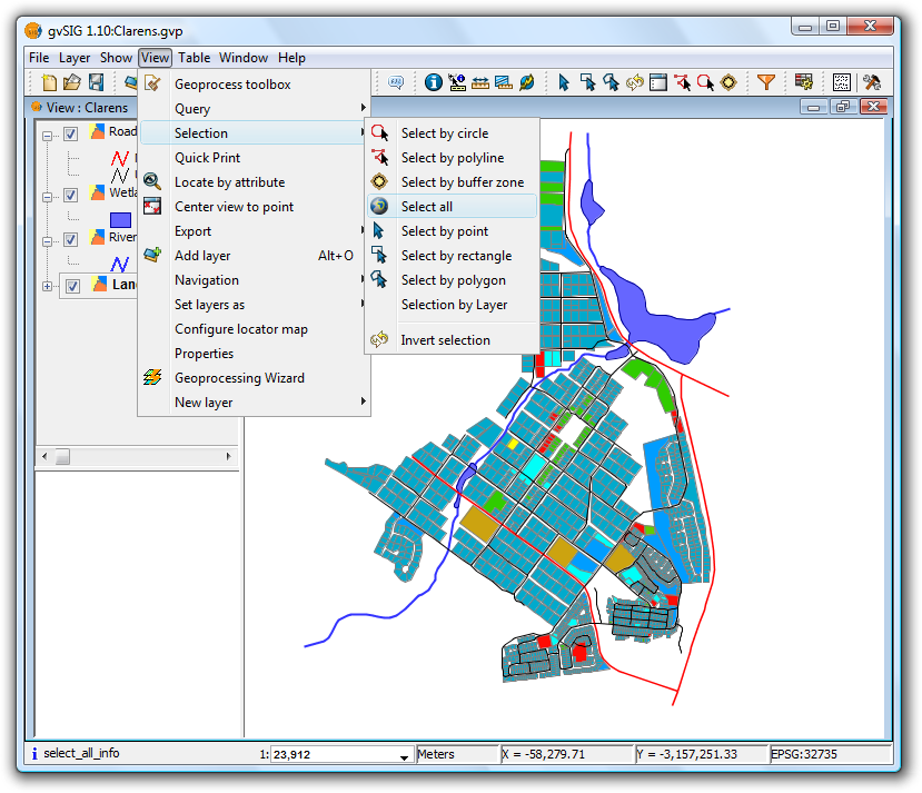
Menu location of Select All tool
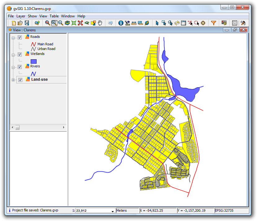
Result of selection
 The tool is not available if the layer is being edited.
SELECT BY POLYLINE
This tool is enabled when there is at least one active vector layer in the TOC.
 "Select by polyline" tool enabled if there are active vector layers in the current View.
 "Select by polyline" tool disabled if there are no active vector layers in the current View.
This tool selects those geometries of the active layers that intersect the polyline defined by the user.
The tool can be accessed in two ways:
- Via the menu: View -> Selection -> Select by polyline
- Via the icon on the toolbar
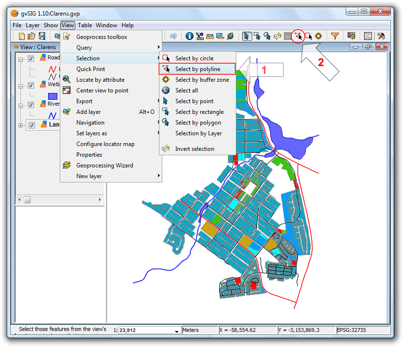
Location of the Select by polyline tool
With the tool selected, move the mouse over the View and enter a series of clicks to define the polyline. Double-click to end the polyline.
Selection using a polyline
 You can use any mouse button to define the points of the polyline, including the final point.
If another polyline is created while holding down the Ctrl key then the geometries thus selected are added to those already selected. If, while doing this, a previously selected geometry is selected again then it will be deselected.
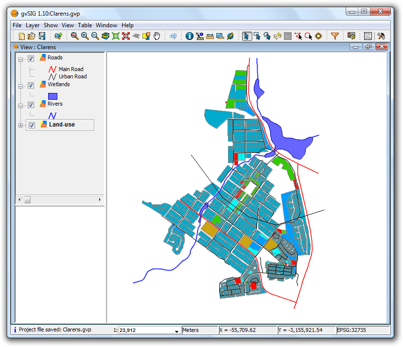
Result of the selection
SELECT BY CIRCLE
This tool is enabled when there are one or more active vector layers in the TOC.
This tool selects geometries (features) of the active layers that intersect the circular area defined by the user.
 "Select by circle" tool enabled if there are active vector layers in the current View.
 "Select by circle" tool disabled if there are no active vector layers in the current View.
The tool can be accessed in two ways:
- Via the menu: View -> Selection -> Select by circle
- Via the icon on the toolbar
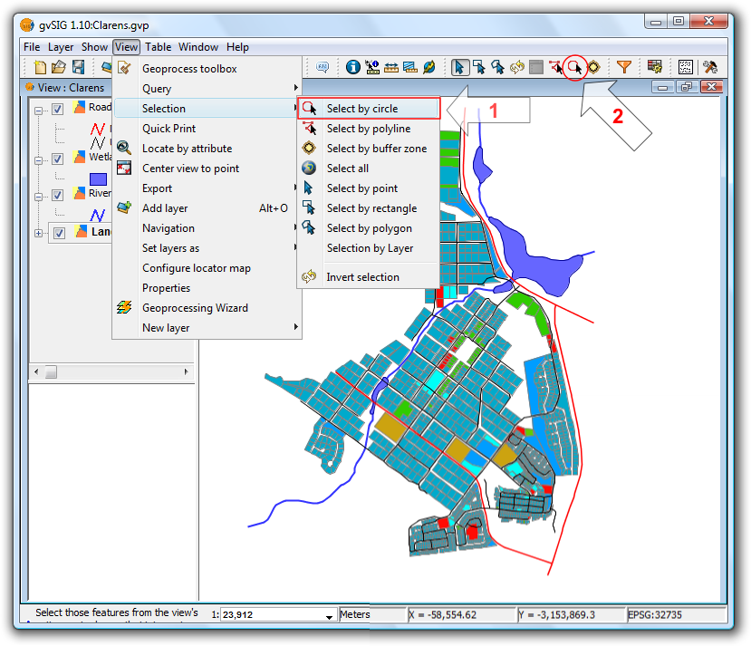
Location of the Select by circle tool
In the View click the mouse at the centre of the circle and then move the mouse outwards to define the size of the circle. Click once to finish drawing the circle.

Selection using a circle
Another circle can be defined while holding down the Ctrl key to add new geometries to those already selected. Previously selected geometries selected again in this manner will be deselected.
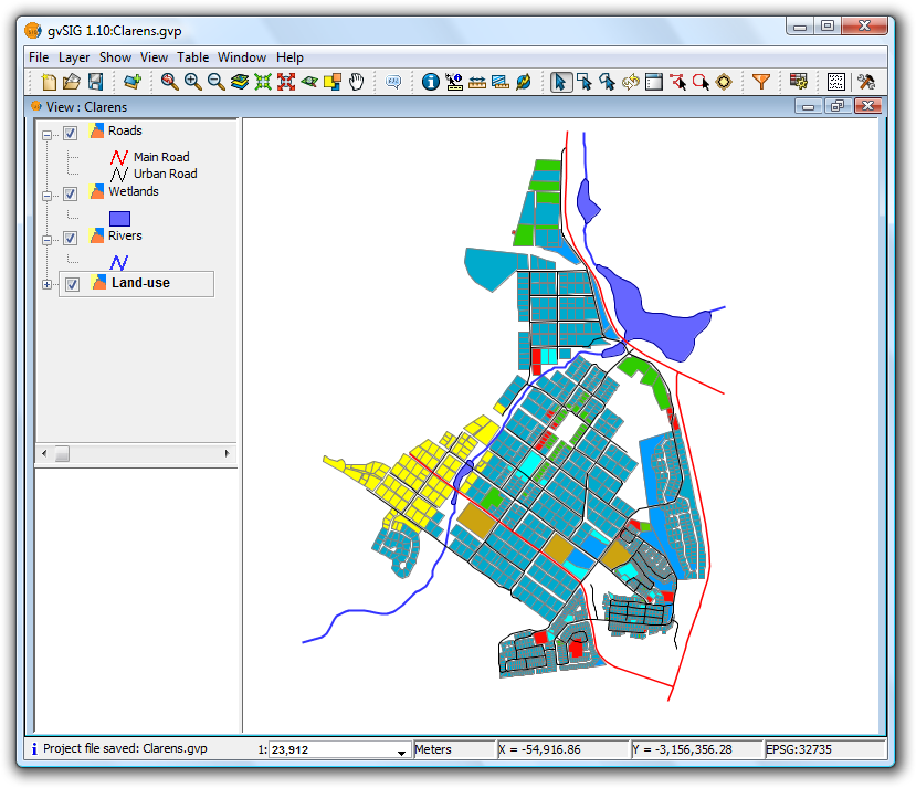
Result of the selection
SELECT BY BUFFER ZONE
This tool is enabled if there is at least one active vector layer in the TOC.
 "Select by buffer zone" tool enabled if there are active vector layers in the current View and these layers have plane coordinates.
 "Select by buffer zone" tool disabled if there are no active vector layers in the current View with plane coordinates.
This tool selects geometries of the active layers that intersect buffer zones around selected geometries.
The tool can be accessed in two ways:
- Via the menu: View -> Selection -> Select by buffer zone
- Via the icon on the toolbar

Location of the Select by buffer zone tool
- Tool requirements
- Vector layers must be active in the TOC
- The selection does not apply to layers with geographical coordinates, only to layers with plane coordinates (e.g. UTM)
- Geometries must be selected in at least one layer
- Configuration panel
When the tool is selected the following configuration panel is displayed:

Configuration options
- Width: width of the buffer zone.
- Unit: units of the buffer zone width.
- Polygon: which side of the polygon to generate the buffer zone:
- Outside: to the outside of the polygon.
- Inside: to the inside of the polygon.
- Line: for line layers the buffer zone will always be towards the outside.
- Point: for point layers the buffer zone will always be towards the outside.
- Multipoint: for multipoint layers the buffer zone will always be towards the outside.
- Multi-layer selection: the selection will apply to all layers that meet the requirements.
- Add buffer zone layers: when selected this option adds the generated buffer zone(s) to the View's TOC.
The new layers are named as follows:
- influence_areas_layername_num
- influence_areas -> prefix to identify this type of layer.
- layername -> name of the layer for which the buffer zone is calculated.
- num -> numerical suffix to identify each new buffer zone layer that is generated, automatically increased for each new zone generated from a single layer, starting from zero.
Example
Let's look at a typical example using the "Select by buffer zone" tool and four layers:
- A shape layer showing "Bird Special Protection Areas" of Castilla y León, obtained from the Ministry of Environment, symbolised with a filled "unique symbol" and with a transparency setting (zepa41):
http://www.mma.es/secciones/biodiversidad/banco_datos/info_disponible/zip/zepa41.zip/
- A shape layer showing "Sites of Community Importance" in Castilla y León, obtained from the Ministry of Environment, and using a unique values symbology:
http://www.mma.es/secciones/biodiversidad/banco_datos/info_disponible/zip/lic41.zip/
- A shape layer shape showing the provinces of Castilla y León, using a unique values symbology.
- A background WMS layer showing hydrographic information, topography, geology, road networks and administrative boundaries in Spain:
WMS Server: http://www.idee.es/wms/PNOA/PNOA/
Layer: PNOA
Style: Default
Format: image/png with transparency and SRS=23030
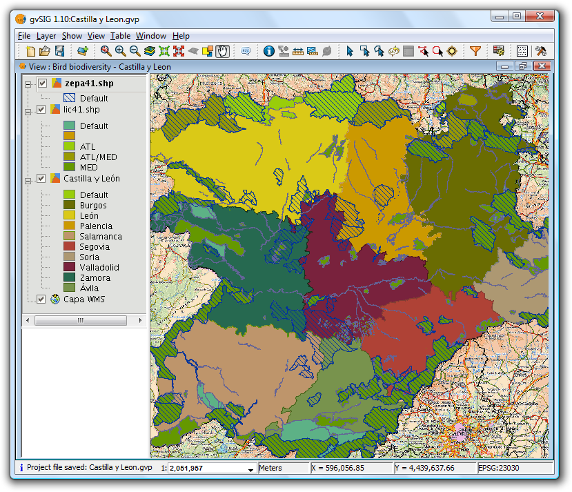
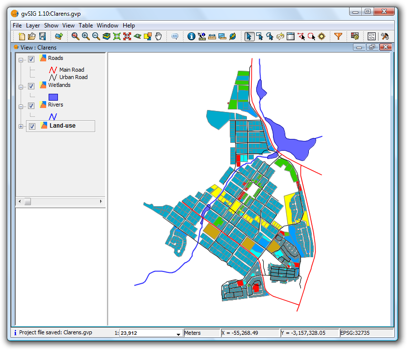
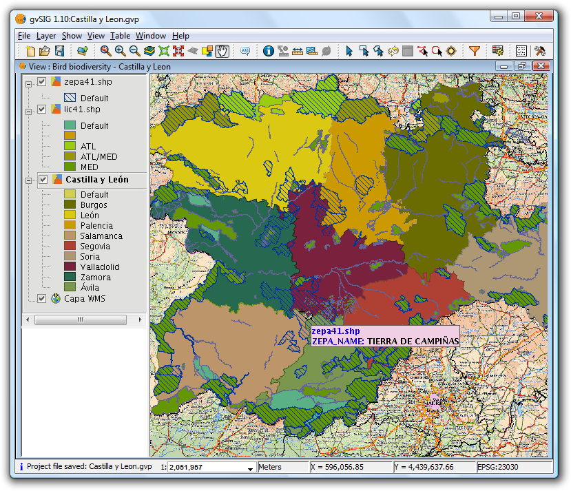
View showing the vector layers, with the Bird Protection Areas layer active
Now select the bird special protection area called "Tierra de Campiñas", which belongs to Valladolid, Ávila and Salamanca. Also select the Site of Community Importance called "Montes Torozos y Páramos de Torquemada – Astudillo" in Valladolid.
View showing the vector layers, with the provinces layers active
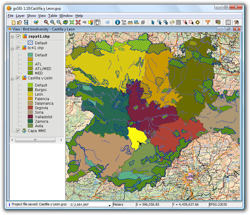
Manual selection of one of the polygons
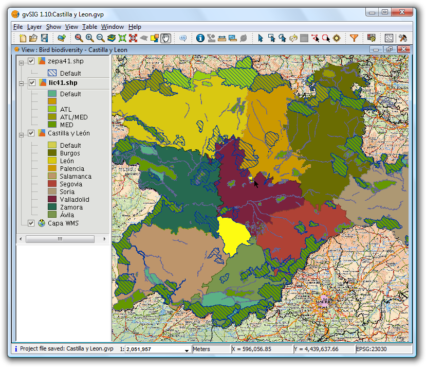
Make the lic41 layer active
Finally, we want to find the areas of type "lic" and "zepa" close to (up to 15 km) the selected areas so that, for example, they can be taken into account in a future second phase involving work to protect birds.
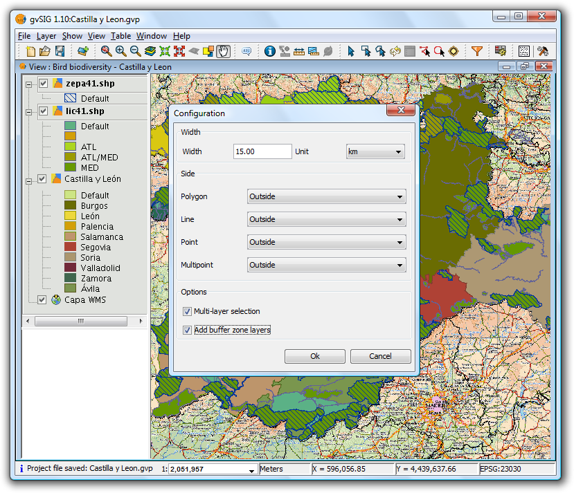
Set options for the buffer zone
The following settings have been applied:
- The zepa41 and lic41 vector layers have been made active.
- Width is set at 15 kilometers.
- The two selected layers are polygon layers, and for this example the buffer zone is set to be outside the polygons.
- Indicate that the selection should be applied to each active layer (Multi-layer selection).
- Finally, add the generated buffer zones as new layers.
The result is shown in the following screenshot. The buffer zones can be turned off so that the selected areas can be seen.
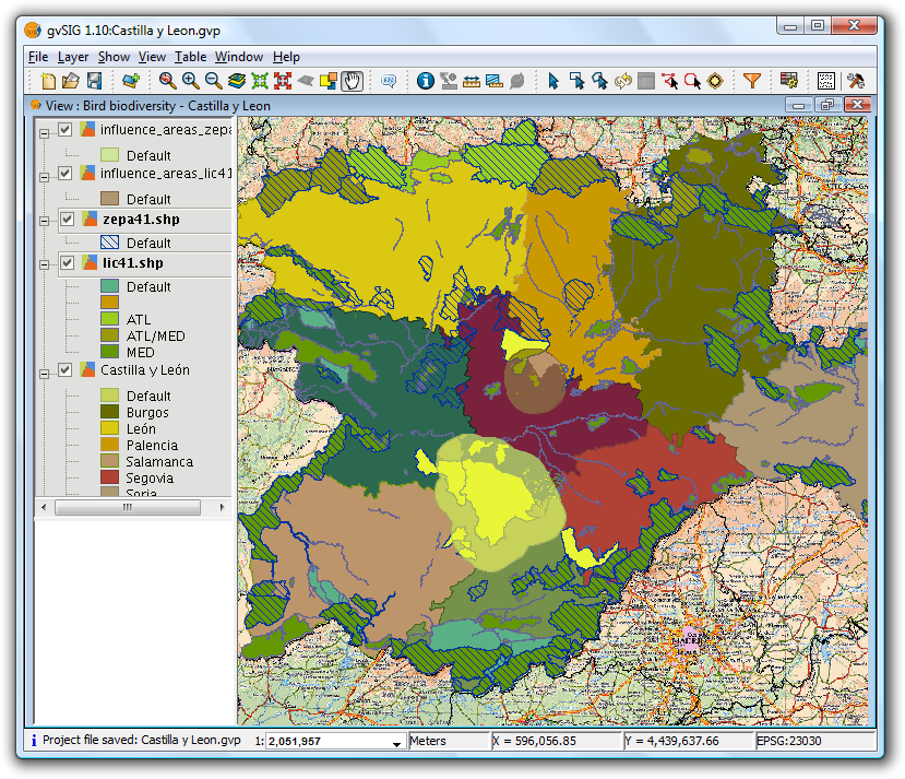
Result of selection by buffer zone
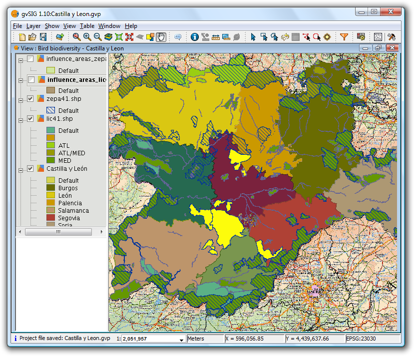
Result with buffer zones switched off
- Details of the process
Click the "Show Details" button below the progress bar to show information on the steps that have been performed, including failures.
Sample output from the above process:
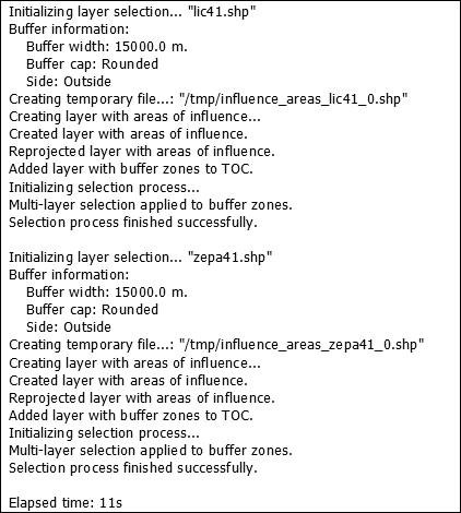
Sample output
Selection is applied to each active layer that meets the requirements.
If the "Multi-layer selection" option is active, then for each buffer zone selections are applied to those layers that also meet the requirements.
If the projection of the layer is not the same as that of the View, an internal reprojection is performed in order to compute the buffer zones. The projection is later restored.
A shape layer is created (one for each active layer that meets the requirements) for storing the buffer zones. The location of each new layer is shown in the line beginning "Creating temporary file".
If the "Add buffer zone layers" option is selected, then the temporary layers are created and added to the TOC, symbolised with a unique symbol and with transparency.
If an active layer is not projected, then the applied selection is discarded.
If a failure occurs, the user is alerted and the selection process is terminated.
 If the process is cancelled, the previous selection state in the affected layers is restored.
Cached time 11/21/13 07:08:12 


